Read A Circuit Diagram : Reading Pnuematic Schematics - YouTube - Power distribution l, component location fusible link dedicated fuse no.. Knowing how to read circuits is a very useful skill that will help you out all the time. Circuit diagrams show the connections as clearly as possible with all wires drawn neatly as straight lines. Our circuit diagram symbol library is schematic and includes many icons commonly used by engineers. A circuit diagram (electrical diagram, elementary diagram, electronic schematic) is a graphical representation of an electrical circuit. Circuit drawings and wiring diagrams this instructable will show you exactly how to read all those confusing circuit diagrams and then how to.
Circuit diagrams, aka schematics, are line drawings that show how a circuit's components are connected together. First, you must find out and learn what the symbols stand for and something about the other things that are on that diagram. From this elementary circuit diagram, you can diagram then build a wide range of electronics projects, from simple light switches and bulbs to sound systems to computers. A circuit diagram is a visual display of an electrical circuit using either basic images of parts or industry standard symbols. A circuit diagram (also known as an electrical diagram, elementary diagram, or electronic schematic) is a simplified conventional graphical representation i have 24 analog channel which gives me 0~5v analog out put.
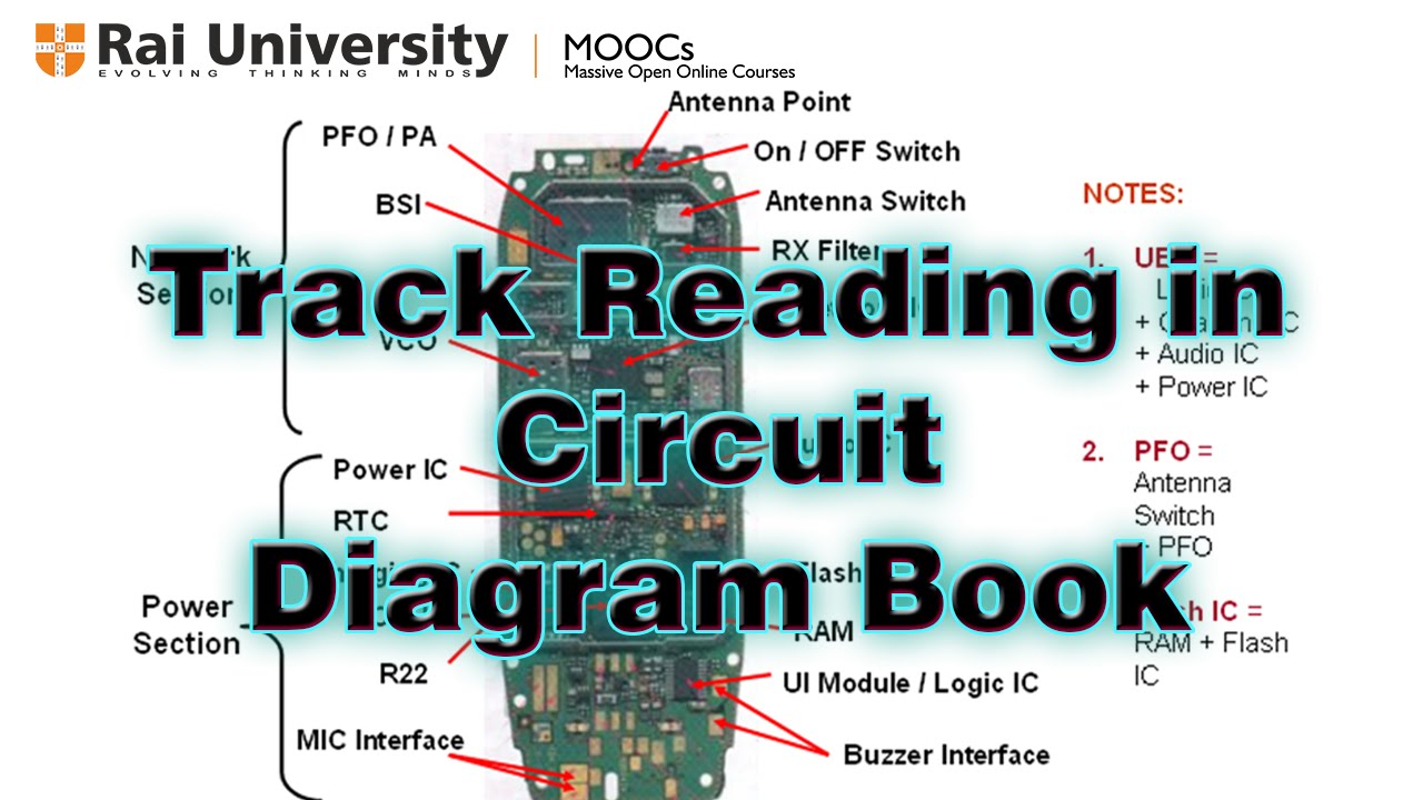
Track reading in circuit diagram - YouTube from i.ytimg.com Circuit diagram.org also provides a full educational system to students new to electronics. Now my problem is i have only 5 analog channel. A circuit diagram (also known as an electrical diagram, elementary diagram, or electronic schematic) is a simplified conventional graphical representation i have 24 analog channel which gives me 0~5v analog out put. It can happen both in ac or dc circuit, if it is an ac. Power distribution l, component location fusible link dedicated fuse no. For you those are not familiar with analog circuits, it might seem difficult to find a practical application of if you continue to use this site we will assume that you are happy with it.ok read more. Learn more about how to make a circuit diagram by reading this circuit diagram tutorial. It's quick, easy, and completely free.
Remark the above circuit diagram shows the current flow at the ignition key position acc.
From this tutorial, you will recognize circuit diagrams symbols and understand electrical schematic learning to read electrical schematics is like learning to read maps. A circuit diagram (electrical diagram, elementary diagram, electronic schematic) is a graphical representation of an electrical circuit. This means that you connect them with a wire. From this elementary circuit diagram, you can diagram then build a wide range of electronics projects, from simple light switches and bulbs to sound systems to computers. The diagram shows some common circuit symbols. Circuit drawings and wiring diagrams this instructable will show you exactly how to read all those confusing circuit diagrams and then how to. Circuit diagram.org also provides a full educational system to students new to electronics. Hello readers, we frequently add new circuit diagrams, so do not forget to come. We use circuit symbols to draw diagrams of electrical circuits, with straight lines to show the wires. They serve as a map or plan for assembling electronics projects, and they are easy to read — far easier than understanding how the circuits they describe actually work. Remark the above circuit diagram shows the current flow at the ignition key position acc. A circuit diagram, or a schematic diagram, is a technical drawing of how to connect electronic components to get a certain function. A circuit diagram shows how electricity flows.
We use circuit symbols to draw diagrams of electrical circuits, with straight lines to show the wires. Hello readers, we frequently add new circuit diagrams, so do not forget to come. Reading schematics is actually pretty easy. Watch this quick tutorial on creating electrical circuit diagrams. Circuit diagrams, aka schematics, are line drawings that show how a circuit's components are connected together.
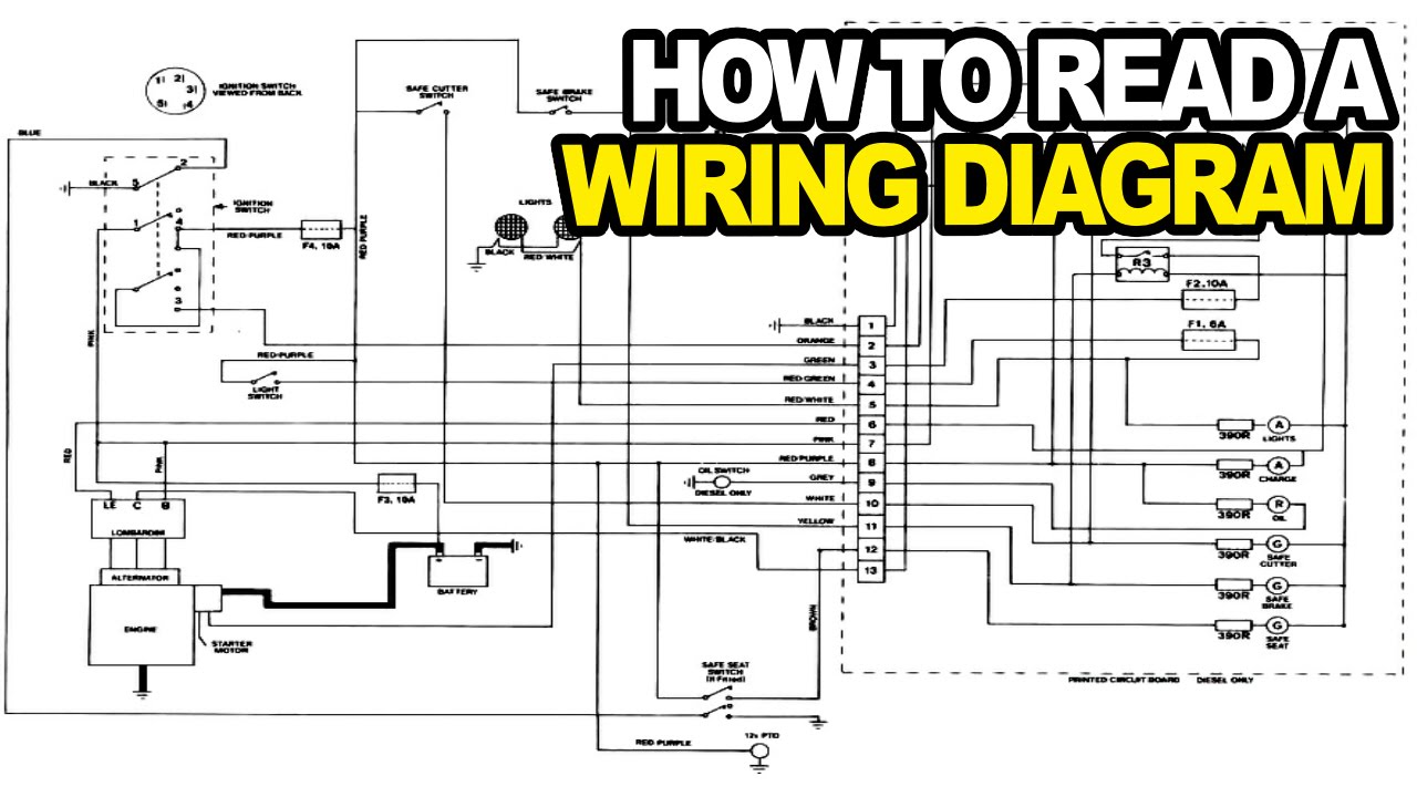
How to: Read an Electrical Wiring Diagram - YouTube from i.ytimg.com Ence of radio beyond turning the knobs. How do you read circuits diagrams? A circuit diagram (electrical diagram, elementary diagram, electronic schematic) is a graphical representation of an electrical circuit. For you those are not familiar with analog circuits, it might seem difficult to find a practical application of if you continue to use this site we will assume that you are happy with it.ok read more. Our circuit diagram symbol library is schematic and includes many icons commonly used by engineers. From transistors to logic gates, you'll find icons that are modeled to international want to make a circuit diagram of your own? This means that you connect them with a wire. These show how the components are connected.
The symbol for a battery is made by joining two more symbols for a cell together.
You have to learn how to read it. Reading schematics is actually pretty easy. I wanted to read value from each. Good circuit diagram design helps ensure that anyone can pick up a diagram and understand clearly what is going on. Watch this quick tutorial on creating electrical circuit diagrams. And the written text of an artiele. All the information present on this site are for personal use only. The symbol for a battery is made by joining two more symbols for a cell together. Vp online's circuit diagram software gets you started quickly and finished fast through a rich set of circuit diagram shape, a wide range of circuit diagram templates and an intuitive ciruit diagram editor. First, you must find out and learn what the symbols stand for and something about the other things that are on that diagram. For example, if something goes wrong with our electronic compass, we usually first check whether the voltage my trick with circuit diagrams is to analyze and examine them in parts, not in whole. A circuit diagram, or a schematic diagram, is a technical drawing of how to connect electronic components to get a certain function. It can happen both in ac or dc circuit, if it is an ac.
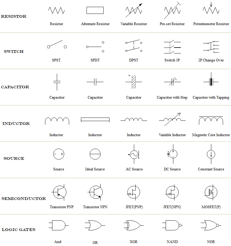
Circuit or schematic diagrams consist of symbols representing physical components and lines representing wires or electrical conductors. The most popular circuit diagrams such as amplifier, fm transmitter, power supply and other. In order to learn how to read a circuit diagram, it is necessary to learn what the schematic symbol of a component looks like. Circuit drawings and wiring diagrams this instructable will show you exactly how to read all those confusing circuit diagrams and then how to. These show how the components are connected.
Tutorial - How to Read Circuit Diagrams from www.edrawsoft.com Circuit diagram.org also provides a full educational system to students new to electronics. A circuit diagram, or a schematic diagram, is a technical drawing of how to connect electronic components to get a certain function. Our circuit diagram symbol library is schematic and includes many icons commonly used by engineers. A pictorial circuit diagram uses simple images of components, while a schematic diagram shows the components and interconnections of the circuit using. A circuit diagram shows how electricity flows. From this elementary circuit diagram, you can diagram then build a wide range of electronics projects, from simple light switches and bulbs to sound systems to computers. First, you must find out and learn what the symbols stand for and something about the other things that are on that diagram. The most popular circuit diagrams such as amplifier, fm transmitter, power supply and other.
No commercial use is permitted without the prior.
All the information present on this site are for personal use only. They are mostly used to draw a circuit diagram and are standardized internationally by the ieee standard (ieee std 315) and the british standard (bs 3939). Knowing how to read circuits is a very useful skill that will help you out all the time. Ence of radio beyond turning the knobs. First, you must find out and learn what the symbols stand for and something about the other things that are on that diagram. A circuit diagram, or a schematic diagram, is a technical drawing of how to connect electronic components to get a certain function. This means that you connect them with a wire. From transistors to logic gates, you'll find icons that are modeled to international want to make a circuit diagram of your own? For example, if something goes wrong with our electronic compass, we usually first check whether the voltage my trick with circuit diagrams is to analyze and examine them in parts, not in whole. A circuit diagram shows how electricity flows. And the written text of an artiele. Ciircuits, diagrams & symbols includes: The diagram shows some common circuit symbols.